This guest post is by Tom Verbeure.
# Introduction
If you’re reading this you probably already know that Yosys is an open source logic synthesis tool. You may also know that it’s much more than that: in my earlier blog post about CXXRTL I call it the swiss army knife of digital logic manipulation.
In most cases, using Yosys
means running pre-made scripts that contain Yosys commands: when I’m synthesizing RTL for an FPGA of the
Lattice iCE40 family, the synth_ice40 command is
usually sufficient to convert my RTL into a netlist that can be sent straight to
nextpnr
for place, route, and bitstream creation.
My current version of Yosys has 232 commands, and many of these commands have an impressive list of additional options, but sometimes you want to perform very particular logic operations that don’t come standard with the tool.
In this blog post, I’ll talk about the techmap command,
a particularly powerful command that allows one to make custom logic transformations by replacing a
logic cell instance of a given type to one or more different ones.
# Mapping a multiplication to an FPGA DSP Cell
There is a companion yosys_techmap_blog project on GitHub that contains the Verilog source files and the scripts to generate the graphics and Yosys results of this blog post.
A good example of a techmap operation is one where a generic multipication
is converted into a DSP block of an FPGA. For those who are unfamiliar with the technology,
FPGAs usually have only a few core logic primitives: lookup-table cells (LUTs) are used to construct
any kind of random logic circuit, RAM cells are, well, RAMs, and DSPs are larger cells that contain one
or more hardware multipliers, often in combination with an accumulator.
Let’s look at this Verilog module, mul.v,
that multiplies two 10-bit values into a 20-bit result:
module top(input [9:0] op0, input [9:0] op1, output [19:0] result);
    assign result = op0 * op1;
endmodule
When reading in the Verilog file, Yosys translates it into RTLIL (RTL Internal Language),
the internal representation of the design. The multiplication operation becomes a $mul primitive,
and the whole design looks like this:
module \top
  wire width 10 input 1 \op0
  wire width 10 input 2 \op1
  wire width 20 output 3 \result
  cell $mul $mul$mul.v:3$1
    parameter \A_SIGNED 0
    parameter \A_WIDTH 10
    parameter \B_SIGNED 0
    parameter \B_WIDTH 10
    parameter \Y_WIDTH 20
    connect \A \op0
    connect \B \op1
    connect \Y \result
  end
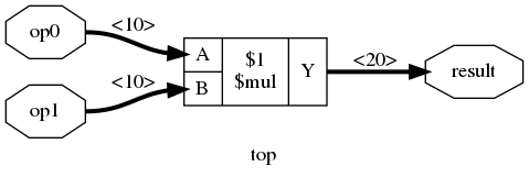
Yosys has the super useful show command
that renders an RTLIL representation as a graph. I usually add the -width -signed options to
annotate signals with their size and to show which cell ports are signed:
This primitive must be converted into cells of the target technology. Most FPGAs from the
iCE40 family have a handful of DSPs. When you synthesize this module to the iCE40 technology with
synth_ice40 -dsp, the $mul primitive gets converted to an SB_MAC16 cell which is the DSP
primitive of the iCE40 family.
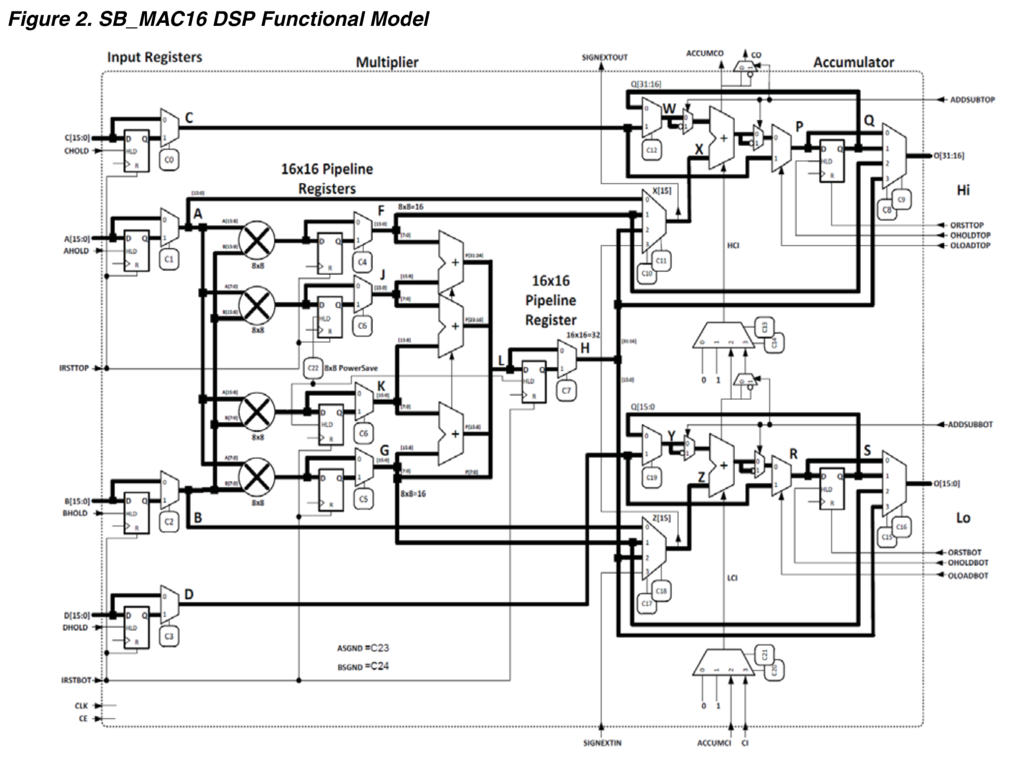
The SB_MAC16 DSP has a ton of data path and configuration signals, and the multiplier inputs and
output can be up to 16 and 32-bits wide respectively. It’s up to a techmap step to assign all the right
values to the configuration signals, and to correctly tie down unused input data bits or ignore excess
output bits so that the DSP performs the desired 10-bit x 10-bit multiplication.
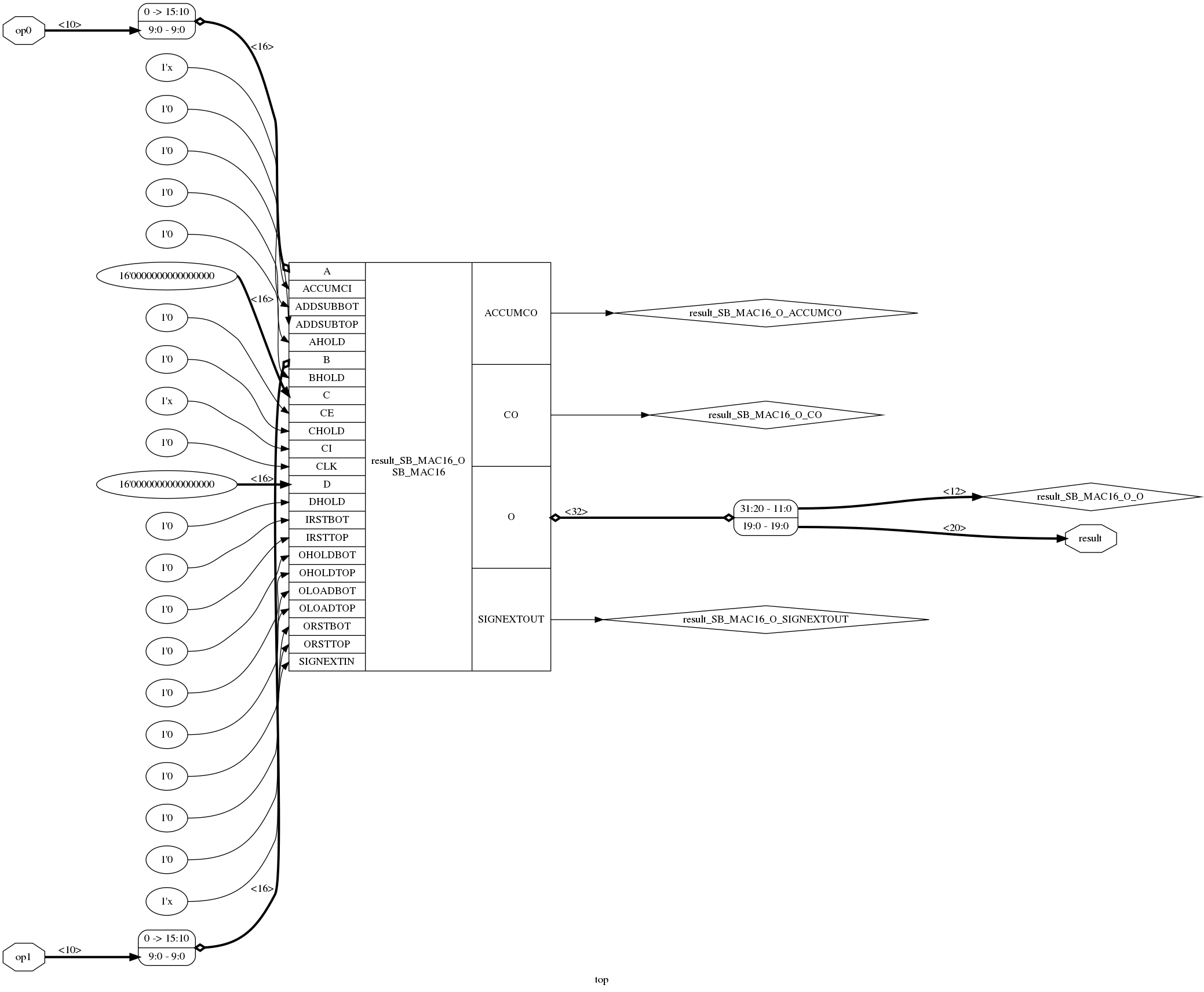
After cleaning up some irrelevant cruft, the post-synthesis RTLIL looks like this:
module \top
  wire width 10 input 1 \op0
  wire width 10 input 2 \op1
  wire width 20 output 3 \result
  wire \result_SB_MAC16_O_ACCUMCO
  wire \result_SB_MAC16_O_CO
  wire width 12 \result_SB_MAC16_O_O
  wire \result_SB_MAC16_O_SIGNEXTOUT
  cell \SB_MAC16 \result_SB_MAC16_O
    parameter \A_REG 1'0
    parameter \A_SIGNED 0
    parameter \BOTADDSUB_CARRYSELECT 2'00
    parameter \BOTADDSUB_LOWERINPUT 2'10
    parameter \BOTADDSUB_UPPERINPUT 1'1
    parameter \BOTOUTPUT_SELECT 2'11
    parameter \BOT_8x8_MULT_REG 1'0
    parameter \B_REG 1'0
    parameter \B_SIGNED 0
    parameter \C_REG 1'0
    parameter \D_REG 1'0
    parameter \MODE_8x8 1'0
    parameter \NEG_TRIGGER 1'0
    parameter \PIPELINE_16x16_MULT_REG1 1'0
    parameter \PIPELINE_16x16_MULT_REG2 1'0
    parameter \TOPADDSUB_CARRYSELECT 2'11
    parameter \TOPADDSUB_LOWERINPUT 2'10
    parameter \TOPADDSUB_UPPERINPUT 1'1
    parameter \TOPOUTPUT_SELECT 2'11
    parameter \TOP_8x8_MULT_REG 1'0
    connect \A { 6'000000 \op0 }
    connect \ACCUMCI 1'x
    connect \ACCUMCO \result_SB_MAC16_O_ACCUMCO
    connect \ADDSUBBOT 1'0
    connect \ADDSUBTOP 1'0
    connect \AHOLD 1'0
    connect \B { 6'000000 \op1 }
    connect \BHOLD 1'0
    connect \C 16'0000000000000000
    connect \CE 1'0
    connect \CHOLD 1'0
    connect \CI 1'x
    connect \CLK 1'0
    connect \CO \result_SB_MAC16_O_CO
    connect \D 16'0000000000000000
    connect \DHOLD 1'0
    connect \IRSTBOT 1'0
    connect \IRSTTOP 1'0
    connect \O { \result_SB_MAC16_O_O \result }
    connect \OHOLDBOT 1'0
    connect \OHOLDTOP 1'0
    connect \OLOADBOT 1'0
    connect \OLOADTOP 1'0
    connect \ORSTBOT 1'0
    connect \ORSTTOP 1'0
    connect \SIGNEXTIN 1'x
    connect \SIGNEXTOUT \result_SB_MAC16_O_SIGNEXTOUT
  end
end
And here’s the equivalent graphical representation. (Click to enlarge)
All Yosys commands are written in C++, but in the case of techmap the specific mapping
operations are described in… Verilog! It’s a very neat system that makes it possible for
anyone to create their own custom mapping operations without the need to touch a line of C++.
Let’s see exactly how that works for our example, and look at the source code of the synth_ice40 command.
Yosys places all the technology-specific operations under the techlibs
directory. The code for synth_ice40 can be found in
techlibs/ice40/synth_ice40.cc.
synth_ice40 doesn’t really have any smarts by itself: it’s a macro command, a series of lower level
Yosys commands strung together into a recipe.
When you run help synth_ice40 in Yosys, you’ll see the following command line option:
    -dsp
        use iCE40 UltraPlus DSP cells for large arithmetic
It’s easy to see which steps are activated in the source code when DSP mapping is enabled:
run("memory_dff" + no_rw_check_opt); // ice40_dsp will merge registers, reserve memory port registers first
run("wreduce t:$mul");
run("techmap -map +/mul2dsp.v -map +/ice40/dsp_map.v -D DSP_A_MAXWIDTH=16 -D DSP_B_MAXWIDTH=16 "
    "-D DSP_A_MINWIDTH=2 -D DSP_B_MINWIDTH=2 -D DSP_Y_MINWIDTH=11 "
    "-D DSP_NAME=$__MUL16X16", "(if -dsp)");
run("select a:mul2dsp", "              (if -dsp)");
run("setattr -unset mul2dsp", "        (if -dsp)");
run("opt_expr -fine", "                (if -dsp)");
run("wreduce", "                       (if -dsp)");
run("select -clear", "                 (if -dsp)");
run("ice40_dsp", "                     (if -dsp)");
run("chtype -set $mul t:$__soft_mul", "(if -dsp)");
There’s quite a bit going on here, but the most interesting command is this one:
    techmap -map +/mul2dsp.v -map +/ice40/dsp_map.v
        -D DSP_A_MAXWIDTH=16 -D DSP_B_MAXWIDTH=16
        -D DSP_A_MINWIDTH=2 -D DSP_B_MINWIDTH=2 -D DSP_Y_MINWIDTH=11
        -D DSP_NAME=$__MUL16X16
What we see here is that techmap is performing the $mul to SB_MAC16 conversion in two steps:
- convert
$multo a generic, technology independent DSP multiplier cell. - convert the generic multiplier DSP cell to an iCE40 DSP cell.
Step 1: mul2dsp.v
Step 1 is done by mul2dsp.v.
The code is a bit convoluted, but it has the answer as to why there’s this intermediate step:
-
it deals with cases where a single
$muloperation requires more than one DSP.For example, a 32-bit x 32-bit to 64-bit multiplication is split into 4 16x16=32 multiplications and some additions.
-
it doesn’t do the conversion when the inputs of the multiplication are too small
This avoids wasting precious DSP resources on something that can be implemented with core logic.
The -D ... arguments of the techmap command specify Verilog defines that are passed to the techmap
file. It’s used to parameterize the conversion process:
-D DSP_A_MAXWIDTH=16 -D DSP_B_MAXWIDTH=16informsmul2dspthat the maximum input size of the DSP is 16 bits.-D DSP_A_MINWIDTH=2 -D DSP_B_MINWIDTH=2 -D DSP_Y_MINWIDTH=11provides the minimum requirements that must be satisfied to do the conversion.-D DSP_NAME=$__MUL16X16provides the name of the generic multiplier cells that should be created.
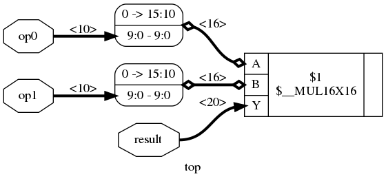
We can run that first step by ourselves and check the result:
read_verilog mul.v
clean -purge
techmap -map +/mul2dsp.v -D DSP_A_MAXWIDTH=16 -D DSP_B_MAXWIDTH=16 -D DSP_A_MINWIDTH=2 -D DSP_B_MINWIDTH=2 -D DSP_Y_MINWIDTH=11 -D DSP_NAME=$__MUL16X16
clean -purge
show -width -signed -format png -prefix mul_mul2dsp
In case you were wondering, here’s what this first step looks like for a 20-bit x 20-bit to 40-bit multiplier:
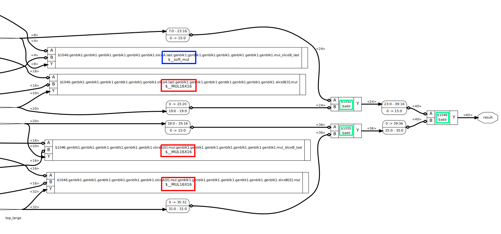 (Click to enlarge)
Yosys can often create very long internal labels that stretch the graphical representation, so
I zoomed the image to the part that counts. The 3 red rectangles are the $__MUL16X16 cells that will be converted
to iCE40 DSPs. The blue rectangle is a $__soft_mul cell that will be converted into random logic
at a large stage, and the 3 green rectangles are $add cells to bring the results of the different multipliers
together.
Step 2: ice40/dsp_map.v
Step 2 of the techmap process, ice40/dsp_map.v
is trivial: it converts the generic $__MUL16X16 multiplier cell into an SB_MAC16 cell, wires up the data path inputs and output,
and straps all the other configuration inputs so that the cell is configured as a straight
multiplier.
module \$__MUL16X16 (input [15:0] A, input [15:0] B, output [31:0] Y);
	parameter A_SIGNED = 0;
	parameter B_SIGNED = 0;
	parameter A_WIDTH = 0;
	parameter B_WIDTH = 0;
	parameter Y_WIDTH = 0;

	SB_MAC16 #(
		.NEG_TRIGGER(1'b0),
		.C_REG(1'b0),
		.A_REG(1'b0),
		.B_REG(1'b0),
		.D_REG(1'b0),
		.TOP_8x8_MULT_REG(1'b0),
		.BOT_8x8_MULT_REG(1'b0),
		.PIPELINE_16x16_MULT_REG1(1'b0),
		.PIPELINE_16x16_MULT_REG2(1'b0),
		.TOPOUTPUT_SELECT(2'b11),
		.TOPADDSUB_LOWERINPUT(2'b0),
		.TOPADDSUB_UPPERINPUT(1'b0),
		.TOPADDSUB_CARRYSELECT(2'b0),
		.BOTOUTPUT_SELECT(2'b11),
		.BOTADDSUB_LOWERINPUT(2'b0),
		.BOTADDSUB_UPPERINPUT(1'b0),
		.BOTADDSUB_CARRYSELECT(2'b0),
		.MODE_8x8(1'b0),
		.A_SIGNED(A_SIGNED),
		.B_SIGNED(B_SIGNED)
	) _TECHMAP_REPLACE_ (
		.A(A),
		.B(B),
		.O(Y),
	);
endmodule
# A Horribly Contrived Example Problem
Have a look at the following Verilog example code:
module top_unsigned(input [5:0] op0, input [6:0] op1, output [63:0] sum);
    assign sum = op0 + op1;
endmodule
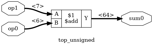
The graphical representation is as expected:

I sometimes use CXXRTL to simulate my designs.
When I run write_cxxrtl, the generated file contains the following:
bool p_top__unsigned::eval() {
	bool converged = true;
	p_sum0 = add_uu<64>(p_op0, p_op1);
	return converged;
}
This is exactly as expected, and there’s nothing wrong with it. But one thing that bothers me is that CXXRTL uses 32-bit integer values (“chunks”) for all its operations. In the code above, there’s a 64-bit addition, and CXXRTL implements those by splitting things up into multiple 32-bit additions:
   template<bool Invert, bool CarryIn>
   std::pair<value<Bits>, bool /*CarryOut*/> alu(const value<Bits> &other) const {
      value<Bits> result;
      bool carry = CarryIn;
      for (size_t n = 0; n < result.chunks; n++) {
         result.data[n] = data[n] + (Invert ? ~other.data[n] : other.data[n]) + carry;
         if (result.chunks - 1 == n)
            result.data[result.chunks - 1] &= result.msb_mask;
         carry = (result.data[n] <  data[n]) ||
                 (result.data[n] == data[n] && carry);
      }
      return {result, carry};
   }
It’s a hand-crafted carry-ripple adder. Now, don’t worry, things are really not as bad as it seems,
because all the variables that are used for the if conditionals and the for loop are constants. Any
good C++ compiler will optimize the addition above into only a few assembler instructions.
If you know your binary adder basics, you see that the addition of a 7-bit and a 6 bit operand will result at most in an 8-bit result. All higher bits will always be 0. It’s overkill to have a 64-bit adder.
Yosys already has the wreduce command that reduces logic
operations to just the number of bits that are really needed.
We can see this when we run the following commands:
read_verilog add.v
hierarchy -top top_unsigned
wreduce
clean -purge
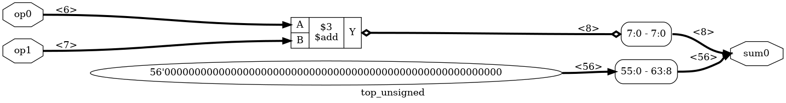
And here’s the relevant CXXRTL generated code:
bool p_top__unsigned::eval() {
    bool converged = true;
    p_sum0.slice<7,0>() = add_uu<8>(p_op0, p_op1);
    p_sum0.slice<63,8>() = value<56>{0u,0u};
    return converged;
}
That looks better, but is that really true? The addition returns an 8-bit value, but since
the smallest chunk is 32-bits, the slice<7,0> command now requires a read-modify-write
operation.
What I really want is this:
bool p_top__unsigned::eval() {
    bool converged = true;
    p_sum0.slice<31,0>() = add_uu<32>(p_op0, p_op1);    <<<<< 32 bits
    p_sum0.slice<63,32>() = value<32>{0u,0u};		<<<<< 32 bits
    return converged;
}
Unfortunately, Yosys doesn’t have a command that does this for me, and I really don’t
want to modify the C++ code of the wreduce command
to make it so.
# A Custom Techmap Transformation to the Rescue!
If you start Yosys, running help techmap will give you an exhaustive list of all the features that
you might ever need. But instead of repeating everything in there, let’s create an add_reduce techmap
transformation to solve the problem of the previous section.
Here are some of the basics of a techmap transformation Verilog module:
-
a techmap transformation only operates on a single design cell.
You can not use
techmapto perform multi-cell optimizations such mapping a$mulfollowed by an$addonto an FPGA DSP has multiply-accumulator support. -
a design cell that is transformed by a techmap is selected by a string that contains a list of cell types that are specified with the
(* techmap_celltype "...")attribute. If the techmap module doesn’t have such an attribute, then it’s determined by the name of the Verilog module. -
by default, a techmap operation will iterate on itself until there’s nothing left that matches.
If a techmap operation replaces an
$addprimitive by a new$addprimitive, techmap will run again on the second one. Without some kind of abort mechanism, this will result in an endless loop!There are multiple ways to avoid such an endless loop though. I’ll get to that later.
-
it’s always a good idea to normalize the configuration on which you want to do the main transformation.
Here’s a good example of what I mean by that: we want to reduce the size of an adder based on the size of its inputs. But an adder has 2 inputs, and if these inputs have a different size, then the transformation will have a different code path depending on which input is largest.
However, an addition is commutative: the order of the inputs doesn’t matter.
It’s easier first do a normalization where the A input is guaranteed to be larger or equal than the B input by swapping the inputs, so that actual reduction transformation only has to deal with one case.
The earlier discussed
mul2dsptechmap module does the same thing.
The add_reduce techmap module declaration
In this example, I want a transformation that only works on an $add instance, so I could
create a techmap Verilog module like this:
module \$add(A, B, Y);
    ...
But I prefer to use a descriptive name for the module and use the (* techmap_celltype ...) option to select
the cell types on which the module operates:
(* techmap_celltype "$add" *)
module add_reduce(A, B, Y);
    ...
The add_reduce techmap module interface
The techmap module interface should be the same as the cell on which it operates. Both the
input/output signals and the parameters must be the same. Yosys has a Verilog file called
simlib.v that
contains the reference simulation modules of all its internal primitives. You can use
this to check out the interface details of particular primitive.
Here’s the one for the $add primitive
module \$add (A, B, Y);

parameter A_SIGNED = 0;
parameter B_SIGNED = 0;
parameter A_WIDTH = 0;
parameter B_WIDTH = 0;
parameter Y_WIDTH = 0;

input [A_WIDTH-1:0] A;
input [B_WIDTH-1:0] B;
output [Y_WIDTH-1:0] Y;
The add_reduce techmap module has the same interface:
(* techmap_celltype = "$add" *)
module add_reduce (A, B, Y);
	parameter A_SIGNED = 0;
	parameter B_SIGNED = 0;
	parameter A_WIDTH = 1;
	parameter B_WIDTH = 1;
	parameter Y_WIDTH = 1;

	(* force_downto *)
	input [A_WIDTH-1:0] A;
	(* force_downto *)
	input [B_WIDTH-1:0] B;
	(* force_downto *)
	output [Y_WIDTH-1:0] Y;
The force_downto attribute ensures that the highest numbered bit of each signal is
the MSB. When this attribute is present, Yosys will automatically swap around the bits of connected
wires so that you don’t need to worry about wackos who use bit 0 as MSB.
add_reduce stop conditions
Since we’re replacing an $add primitive with another $add primitive, we need to make sure that
there are special conditions to prevent the techmap operation to run forever.
We can tell the techmap command to stop transforming the current cell instance
by assigning a non-zero value to the _TECHMAP_FAIL_ wire:
wire _TECHMAP_FAIL_ = 1;
For this operation, we want stop transforming an $add primitive for a number of conditions:
-
when the size of the adder is already equal or smaller than the minimal desired adder.
We can set the minimum size with the `Y_MIN_WIDTH define.
-
When the size of the adder can’t be reduced because it would change the result of the calculation.
-
When it’s a signed addition and we only want to transform unsigned additions.
The `REDUCE_SIGNED define must be set to allow signed adder transformation.
This translates into the following code:
    localparam SIGNED_ADDER = (A_SIGNED == 1 && B_SIGNED == 1);

    generate
        if (Y_WIDTH <= `Y_MIN_WIDTH) begin
            wire _TECHMAP_FAIL_ = 1;
        end
        else if (Y_WIDTH <= A_WIDTH+1) begin
            wire _TECHMAP_FAIL_ = 1;
        end
        else if (SIGNED_ADDER && !`REDUCE_SIGNED) begin
            wire _TECHMAP_FAIL_ = 1;
        end
        ...
There are other ways to prevent techmap to run forever. For example, in the mul2dsp.v code,
a $__soft_mul cell used instead of a $mul primitive. Yosys has no such primitive, but
in a later step, after techmap has been completed, this $__soft_mul cell is converted
back to a $mul$ cell:
chtype -set $mul t:$__soft_mul
add_reduce normalization
The normalization code of add_reduce is pretty much a straight copy of the one
from mul2dsp:
    generate
	...
	else if (B_WIDTH > A_WIDTH) begin
            \$add #(
                .A_SIGNED(B_SIGNED), <<< A and B are swapped
                .B_SIGNED(A_SIGNED), <<<
                .A_WIDTH(B_WIDTH),   <<<
                .B_WIDTH(A_WIDTH),   <<<
                .Y_WIDTH(Y_WIDTH)
            ) _TECHMAP_REPLACE_ (
                .A(B),               <<<
                .B(A),               <<<
                .Y(Y)
            );
	end
	else if ...
When using _TECHMAP_REPLACE_ as instance name of the swapped $add primitive, it
will inherit the instance name of the original instance. This is one of the
many predefined variables that are explained by running help techmap in Yosys.
Since we replace $add with $add, running techmap will result in the
$add cell being transformed twice times if B is larger than A: the first time
to swap the inputs, and the second time for the actual reduction.
If techmap needs to transform the same cell multiple times, it can
be hard to debug. You can use the -max_iter <number> option to limit
the number of transformations.
For example, here’s what the design originally looked like:
And here’s how things look when stopping the add_reduce operation after the
first iteration:
techmap -map add_reduce.v -max_iter 1
clean -purge
op1 with the largest input size of 7 is now connected to A!
The actual add_reduce transformation
Now that all preliminary formalities are behind use, the actual reduction code is pretty straightfoward:
else begin
    localparam ADDER_WIDTH  = `MAX(`Y_MIN_WIDTH, A_WIDTH+1);

    \$add #(
        .A_SIGNED(A_SIGNED),
        .B_SIGNED(B_SIGNED),
        .A_WIDTH(A_WIDTH),
        .B_WIDTH(B_WIDTH),
        .Y_WIDTH(ADDER_WIDTH)
    ) _TECHMAP_REPLACE_ (
        .A(A),
        .B(B),
        .Y(Y[ADDER_WIDTH-1:0]) 	// Reduced output size
    );
    // Higher bits are 0 or sign extension
    assign Y[Y_WIDTH-1:ADDER_WIDTH] = { (Y_WIDTH-ADDER_WIDTH){SIGNED_ADDER ? Y[ADDER_WIDTH-1] : 1'b0} };
end
The final add_reduce.v code can be found here.
We can run the whole thing with:
techmap -map add_reduce.v -D Y_MIN_WIDTH=32
clean -purge
The result is exactly what we wanted, as shown in the graphical diagram…
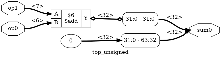
…and in the CXXRTL-generated code:
bool p_top__unsigned::eval() {
	bool converged = true;
	p_sum0.slice<31,0>() = add_uu<32>(p_op1, p_op0);
	p_sum0.slice<63,32>() = value<32>{0u};
	return converged;
}
# Formal Equivalence Check
Whenever you do logic transformations, it’s not a bad idea to check that the pre- and post-transformation logic behaves exactly the same. Yosys has a basic built-in equivalence checker. It’s not a performance monster, but it’s good enough for this kind of use case.
In the example below, I’m verifying the add_reduce techmap on a design with an adder that
has an output that’s 10 instead of 64 bits, and the minimum size is set to 8.
This makes the size of the graphs more managable.
# Load the original design
read_verilog add.v
hierarchy -top top_unsigned10
rename top_unsigned10 top_unsigned

# Make a golden reference copy of the unmodified design
copy top_unsigned top_unsigned_gold

# Select the original version to do the techmap
select top_unsigned

# Do the techmap on top_unsigned
techmap -map add_reduce.v -D Y_MIN_WIDTH=8
clean -purge
So far, so good: Yosys now has 2 designs. top_unsigned_gold is the original one:
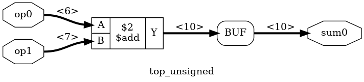
And top_unsigned has been transformed with the techmap:
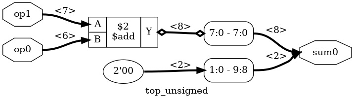
Let’s compare them:
equiv_make top_unsigned_gold top_unsigned top_equiv
select top_equiv
The equiv_make has the golden and the transformed design as input and creates a new
design with $equiv primitive cells inserted at the output of both designs. These cells
will tell the equivalence checker which nets to check for formal equivalence. The
new design top_equiv looks like this:
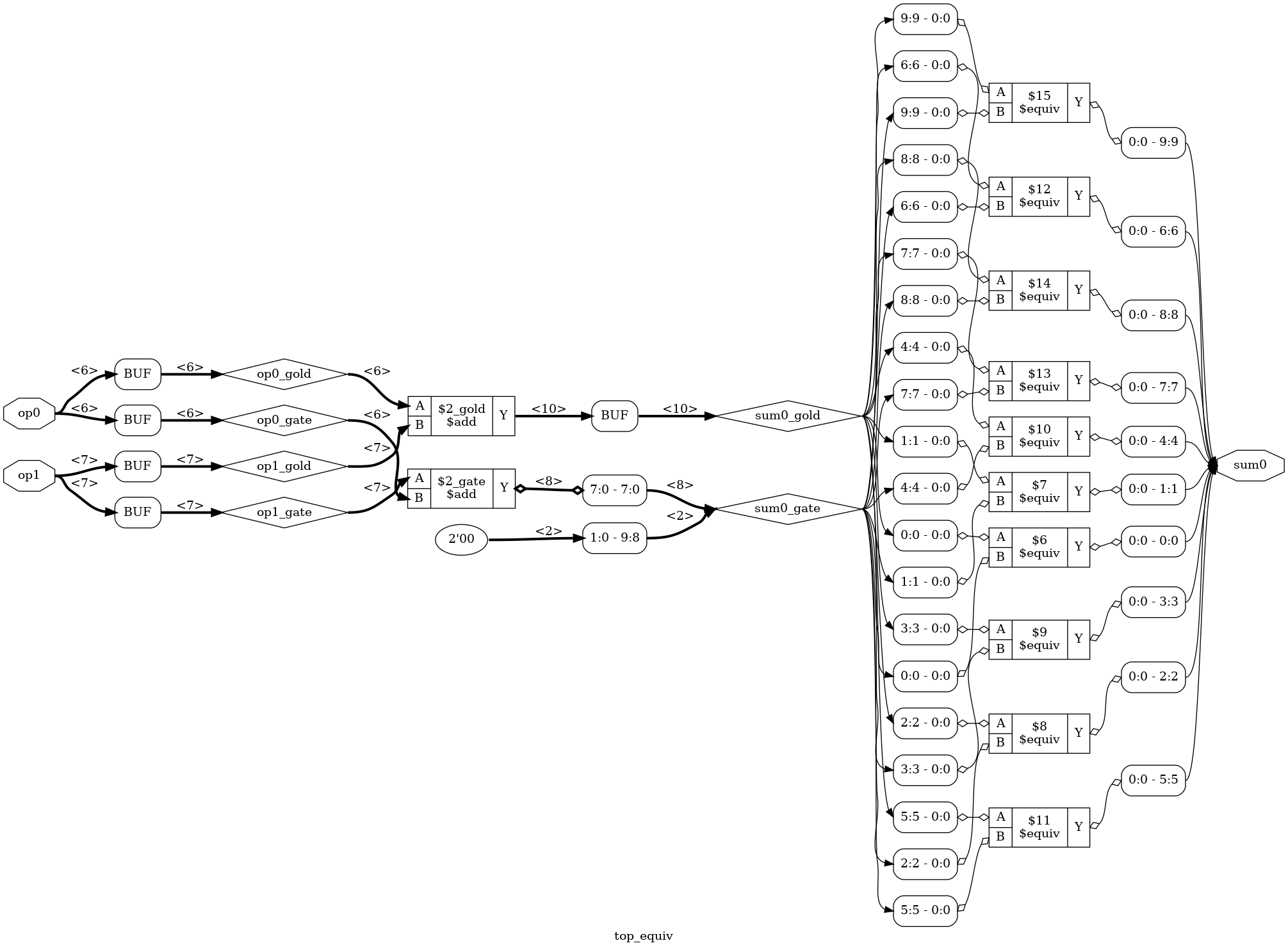 (Click to enlarge)
As you can see, the new design has both the golden and the transformed logic on the left,
driven by the same inputs. For there are 10 $equiv cells, one for each bit of the output.
We can now run the equivalence check:
equiv_simple
You’ll see something like this:
8. Executing EQUIV_SIMPLE pass.
Found 10 unproven $equiv cells (1 groups) in top_equiv:
 Grouping SAT models for \sum0:
  Trying to prove $equiv for \sum0 [0]: success!
  Trying to prove $equiv for \sum0 [1]: success!
  Trying to prove $equiv for \sum0 [2]: success!
  Trying to prove $equiv for \sum0 [3]: success!
  Trying to prove $equiv for \sum0 [4]: success!
  Trying to prove $equiv for \sum0 [5]: success!
  Trying to prove $equiv for \sum0 [6]: success!
  Trying to prove $equiv for \sum0 [7]: success!
  Trying to prove $equiv for \sum0 [8]: success!
  Trying to prove $equiv for \sum0 [9]: success!
Proved 10 previously unproven $equiv cells.
Each individual bit has been proven to be correct.
We can make Yosys fail if there were any unproven $equiv cells, like this:
equiv_status -assert
However, in our case, all is well:
9. Executing EQUIV_STATUS pass.
Found 10 $equiv cells in top_equiv:
  Of those cells 10 are proven and 0 are unproven.
  Equivalence successfully proven!
We’ve now proven that our add_reduce techmap is correct, but that doesn’t mean
it’s guaranteed bug free: we’ve only tested one combination of input and output
signal sizes. To be absolutely sure, you’d need more variety of test cases.
This is only a quick example of what Yosys can do, there’s a variety of additional
equivalence and logic proof features, most of which I don’t know much about! You
could start by checking out the help information for the equiv_*, miter, and sat
commands to learn more.
# Cleaning Up
When Yosys creates new cells and reconnects wires, it won’t immediately delete older cells and wires
that aren’t used anymore. You need to expliclity tell Yosys to do so with the clean -purge
command that you can see in some of the command sequences above.
Here’s what the reduced adder looks like without first running a clean:
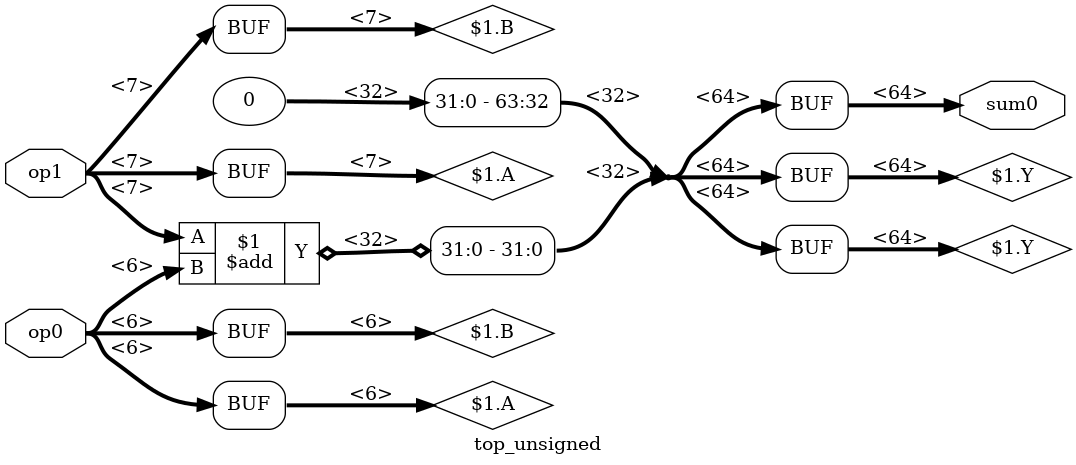
That’s why you see a clean -purge statement all over the place
in the script
generates all the pretty pictures of this blog post.
# Conclusion
Techmap is a very nice tool to have to transform single cells into something that better maps to your chosen target. The example that I’ve given here is a bit dumb (I’m not even sure if it would actually result in better compiled CXXRTL code!), but it shows some of the potential of what can be achieved.
I have only scratched the surface of what can be done with it: there are ways to make a techmap
module behave differently based on whether or not certain input bits are constant, you can
instruct Yosys to run another Yosys command after performing a techmap iteration, and
so forth.
If you want to go deeper, you should definitely start by checking out the help instructions, not
only of techmap command, but also some of the other ones.
# References
-
yosys_techmap_blog repo on GitHub
Contains the Verilog code and the Yosys scripts to generate all the graphs of this blog post.