This is a guest blog post by Hendrik Folmer
# The FPGA “Hello World”
Imagine you’re a first-year engineering student. Today is your very first FPGA development lecture.
The professor starts with an inspiring introduction: “Unlike CPUs, FPGAs don’t execute instructions one after another. You design hardware itself. Thousands of operations can happen in parallel. You describe logic, and the FPGA becomes the circuit you designed.”
Amazing.
You’re told about lookup tables, routing, timing, placement, and the incredible flexibility of programmable hardware. It feels like digital LEGO with millions of pieces.
You can’t wait to build something.
At the end of the lecture, the assignment seems refreshingly simple. “Before next week’s lab, synthesize a blinking LED. It’s the FPGA equivalent of Hello World.”
Perfect. How hard can one blinking LED be?
You get home, open your laptop, and Google:
“Download Quartus.”
The first result looks right.
Download size?
80 GB.
That’s… larger than some games.
Fortunately, your university recommended an expensive laptop with plenty of storage, so after a while the download finally completes.
You click Install.
Disk space required:
299.44 GB.
Well… that’s almost your SSD.
After another long wait, Quartus finally launches.
A popup immediately appears.
License required.
License?
Nobody mentioned a license.
You ask your classmates.
Nobody knows.
You message the teaching assistant.
“Oh… you installed Quartus Pro.”
“You only need Quartus Lite.”
Right.
So you uninstall the 300 GB installation.
Delete the 80 GB installer.
And start over.
Back to Google.
“Download Quartus Lite.”
Much better.
Only a 1.6 GB download.
Installation finishes.
Only 8.8 GB installed.
Progress.
You create your first project.
The wizard asks you to select your target FPGA.
The device list is empty.
Empty.
You ask another student.
“Oh yeah, you also need the device files.”
Of course you do.
Back to Google.
You find the Cyclone V device package.
Only 500 MB.
Easy.
You install it.
Version mismatch.
Wait…
Device files have versions?
Apparently yes.
Not only do they have versions, they must exactly match the Quartus version.
Down to the last digit.
Fine.
You finally locate the correct version.
Just before pressing Download, you notice another dropdown.
Lite / Standard / Pro
That would have been the wrong download. Again.
The correct device package?
Another 1.3 GB.
Several hours after starting this adventure, you finally have a working FPGA development environment.
Now the real learning can begin.
Right?
You launch Quartus.
Create a project.
Select the correct device.
Add a VHDL file called blinky.vhd that you found somewhere online.
You look for the Compile button.
Eventually you find a promising green triangle.
Click.
Error: Top-level entity not specified.
Top-level entity?
What’s a top-level entity?
Why do I need one?
After some searching, you discover the setting.
Compile again.
Success!
Well…
Almost.
183 warnings.
Is that good?
Bad?
Normal?
Did anything actually work?
The software mentions timing analysis.
Clock domains, Latch inference, Constraints, Pin assignments, Clock frequencies.
None of those words were in today’s lecture.
You spend another hour trying to figure out where to tell the compiler your clock frequency.
Eventually you stop and ask yourself: Wasn’t today’s assignment just to blink an LED?
This isn’t an unusual story.
In fact, it’s the most common story.
When I ask students about their first FPGA course, the answer is remarkably consistent.
“Hardware design is fascinating… but the tooling was awful.”
That’s unfortunate.
Because students don’t remember the excitement of designing digital hardware.
They remember spending an evening downloading software, installing device packages, fighting version mismatches, and deciphering hundreds of warnings before writing ten lines of code.
The tooling became the course.
It doesn’t have to be this way.
As educators, we can lower the barrier without lowering the standard.
Students should spend their first hours learning hardware concepts, not wrestling with installers.
That’s why we built EDAcation. Because the first lesson in digital design shouldn’t be how to download 300 GB of tools to blink an LED.
# The synthesis path introduced and visualized
EDAcation is a Visual Studio Code extension that brings an open source FPGA toolchain into a single, student-friendly environment. It combines synthesis, place-and-route, and visualization in a straightforward workflow. The goal is to make the underlying hardware design process visible and understandable, while hiding much of the complexity of the traditional toolchain. One click to generate an RTL schematic. One click to synthesize. One click to place and route. Instead of hiding intermediate results in lengthy reports, EDAcation visualizes them, helping students understand how their hardware description is transformed into a physical FPGA implementation.
# Getting started
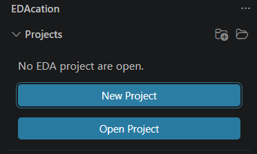
Installing EDAcation is straightforward. Open the Visual Studio Code Marketplace, search for EDAcation, and click Install. Once you open a project folder in VS Code, the EDAcation interface becomes available through the EDA button in the sidebar.
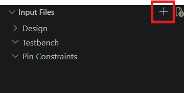
From there, you can create a new project, add your source files, and start exploring your design by clicking RTL.
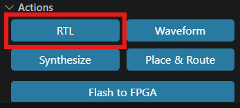
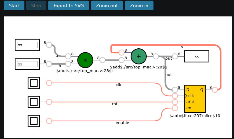
An RTL schematic is generated and displayed immediately. Different hardware elements are represented by different colors, while modules in the design hierarchy are shown in blue boxes. The schematic viewer also supports simulation. Although the simulator is not particularly fast, it is sufficient for small designs and serves its educational purpose: helping students connect their HDL code to the behavior of the hardware they have described.
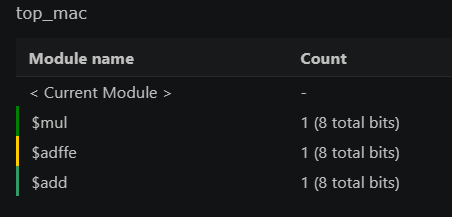
An overview of the design’s components is available in the Stats Viewer. It uses the same color scheme as the RTL schematic, making it easier to connect the visual representation of the design to the resources it contains.
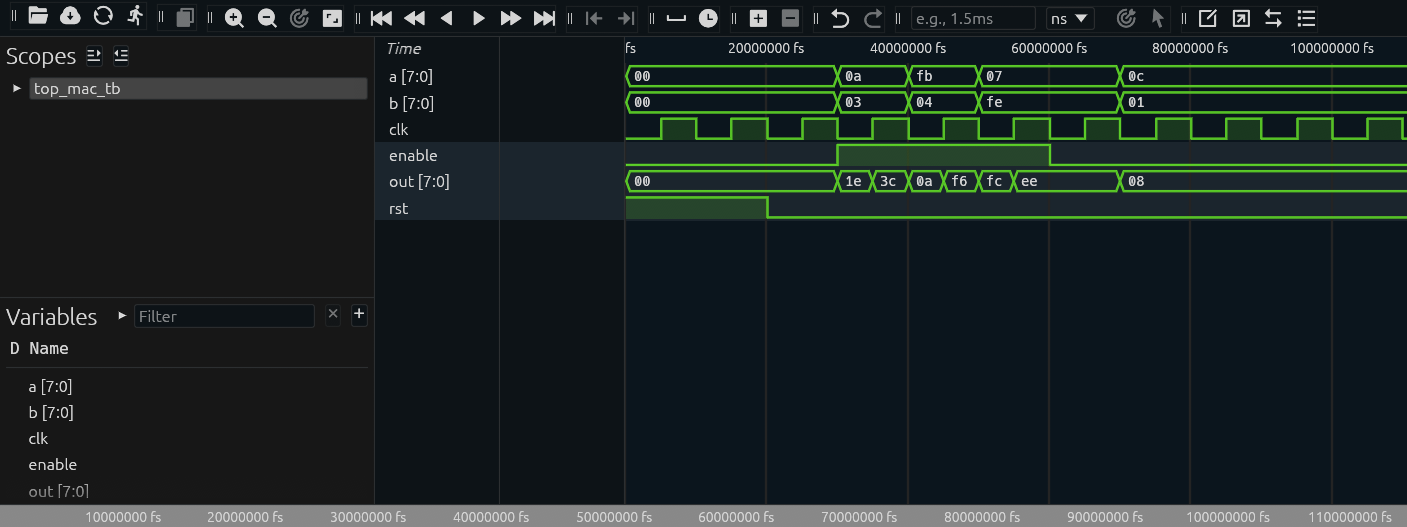
If you add a testbench to the project, you can also generate a waveform. With a single click, the waveform is displayed, allowing students to inspect signal behavior over time and compare it with their expectations.
# From RTL to LUTs
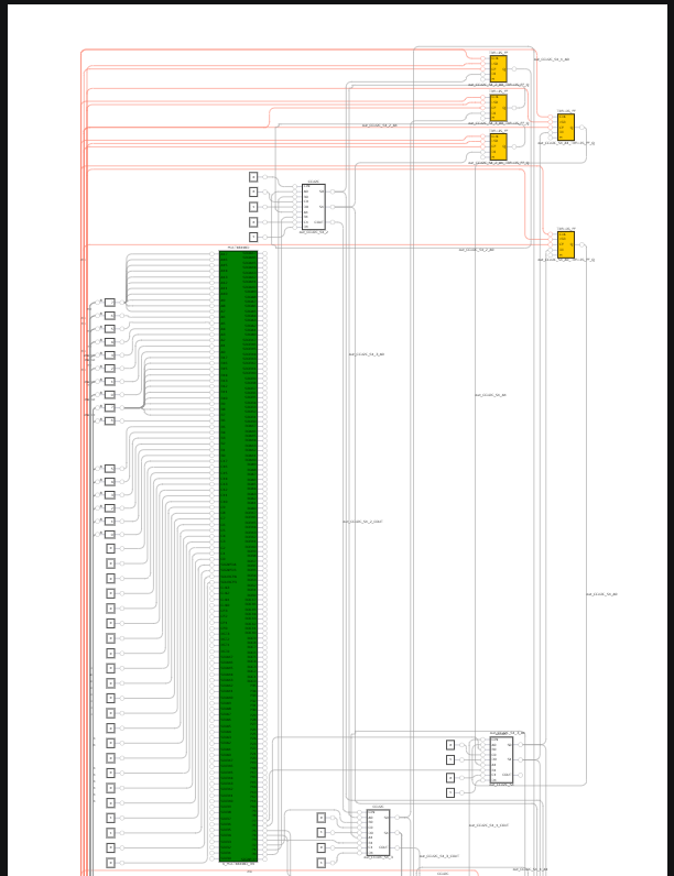
The next step is Synthesis. During logic synthesis, the design is transformed into a representation suitable for implementation on the target FPGA. EDAcation visualizes the resulting lookup table (LUT) structure, giving students a closer look at how their original RTL description becomes hardware.
This is an important step in understanding digital design. Students can see how the schematic is mapped to LUTs and begin to develop an intuition for the size and complexity of their designs.
Rather than treating synthesis as a mysterious process that produces a success message or an error report, EDAcation makes the result tangible.
# Placing and routing the design
The fourth step in the workflow is Place and Route. At this stage, the synthesized design is mapped onto the FPGA’s available resources. Nextpnr determine where the logic elements should be placed and how they should be connected. EDAcation then visualizes the resulting implementation.
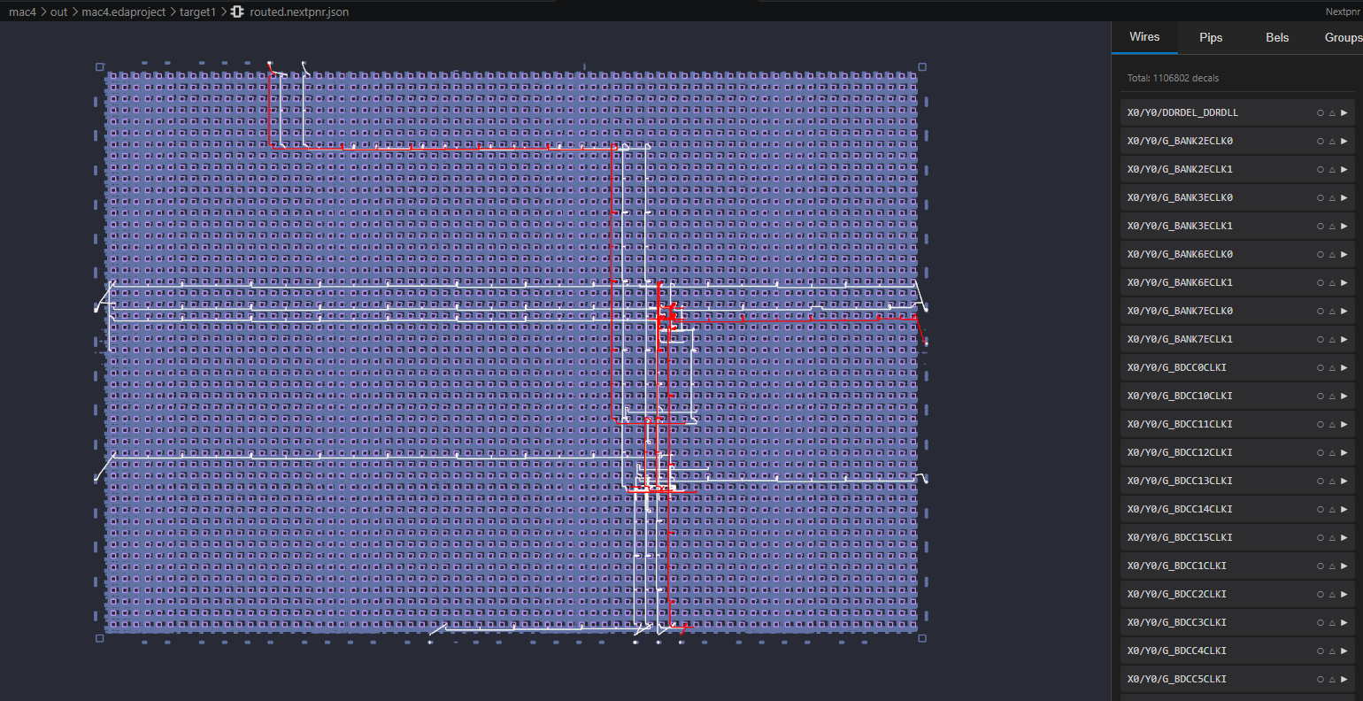
The visualization uses the same colors as the RTL schematic, helping students follow the transformation from their original design to its implementation on the FPGA. They can see where resources such as DSP blocks, registers, and LUTs are placed, making the relationship between the logical design and the physical device more apparent.
The longest combinational path is highlighted in red. This provides a visual starting point for exploring timing behavior and understanding why the arrangement and connections of logic matter, not just the logic itself.
EDAcation also provides a visual interface for working with pin constraints. When a pin constraint file is available, students can inspect and modify the assignments in a graphical environment rather than editing the file by hand.
Once the design is ready, the FlashToFPGA button provides a direct route to programming the device. If the FPGA is recognized by the operating system and VS Code has the necessary permissions, programming the device is as simple as clicking the button.
This completes the workflow, taking students from an HDL description to a design that can run on real hardware, all within the same environment.
# Configuration and flexibility
Of course, not every user has the same requirements. EDAcation therefore provides several configuration options, ranging from the target FPGA type to manually specifying arguments for Yosys and nextpnr.
Users can choose between WebAssembly-based tools, binaries bundled with the extension, or their own locally installed binaries. This flexibility makes EDAcation accessible to beginners while still providing options for more advanced users who want greater control over their toolchain.
There is, however, a balance to strike. Feature creep is always a risk, especially for a project intended to make complex tools easier to understand.
The primary goal of EDAcation is not to replace every feature of established FPGA development environments. It is to provide an educational alternative that emphasizes clarity through visualization.
By making intermediate synthesis results and implementation details visible, EDAcation aims to help students understand what the tools are doing, rather than simply teaching them which buttons to press.
# Built on the shoulders of the open source community
EDAcation would not be possible without the open source projects on which it builds. We have not reinvented the FPGA toolchain; instead, we bring existing tools together and focus on making their results easier to explore and understand.
A big thank-you goes to the developers and communities behind these projects. Their work makes tools like EDAcation possible.
At the moment, further development of EDAcation is on hold. However, the project remains open source, and we have tried to document its architecture and design decisions to make it easier for others to understand how it works and contribute.
We welcome anyone interested in educational hardware design, FPGA tooling, or visualization to explore the project and help take it further.
After all, the goal is simple: students should spend less time fighting their tools and more time understanding the hardware they build.