This guest post is by Bastian Löher.
# How I went from blinker to RISC-V in 3 months
How does one get started with programming FPGAs (field-programmable gate arrays)? Where does one even begin? Also, if you’ve ever wondered how a CPU works and how you can build your own, keep reading!
TL;DR: Getting into FPGA programming nowadays isn’t hard anymore. Get a cheap board with at least one LED that is supported by an open toolchain, search for a tutorial, and get that LED blinking!
# Introduction
As an experimental physicist, I have been working with FPGAs for many years. These versatile devices enable creating customized electronics for all kinds of applications. FPGAs typically contain thousands of mostly simple logic units that can be connected in sophisticated ways using a hardware description language (HDL). I have experience writing efficient software for low-latency embedded processors and have so far only made small adjustments to existing VHDL or Verilog projects. However, only recently have I had the opportunity to take a deeper dive into writing new logic designs from scratch.
It does not feel that long ago that FPGA boards were prohibitively expensive devices, and the tools and IP cores were not accessible to everyone. Starting development for FPGAs used to be a costly investment and close to impossible to do on a small budget. Luckily, this situation has changed. Small FPGA chips now sell for as low as $10, and a lot of development is done on free and open-source toolchains. As it turns out, with enough ambition and a bit of courage, one can achieve reasonable results in FPGA-land today without breaking the bank!
# First, find a project
For me, it all started with a new project that involved creating a device capable of measuring arrival time and length of logic signals with sub-nanosecond precision. The idea was to create a low-cost spectrometer for measuring high-intensity gamma radiation and replacing the commonly used ADC (analog-to-digital converter) circuit with a TDC (time-to-digital converter) implemented in an FPGA. So, instead of measuring the amplitude of the signal, only the time the signal spends above a certain threshold (time-over-threshold) is measured. This design reduces the system complexity but requires custom logic.
# Choose your tools
I have seen many projects written in VHDL and Verilog, but for this one, I wanted to try one of the new HDL alternatives. My language of choice happened to be the Python-based Amaranth HDL (formerly known as nMigen), primarily because I had in mind to write the accompanying firmware for the device in MicroPython. I was also intrigued by Clash and SpinalHDL, but Amaranth seemed to have an easier learning curve. So, with the clear goal of creating a working TDC, I jumped headfirst into writing Amaranth code. Over the course of the next year (where I spent most of the time on system design and writing software), I became more familiar with the language and successfully finished the project on time for our customer.
# Set priorities
While I was working on the project, I encountered many excellent resources and introductory courses for FPGA programming and logic design, and I read various code examples in different HDLs. I also questioned whether Amaranth was the right choice or if I should have chosen a more conventional language. One tutorial that particularly captured my attention was Bruno Levy’s “Blinker to RISC-V”. The concept intrigued me; one starts with an innocent and all-too-familiar ‘blinky’ example but ends up with a fully functional RISC-V CPU that can run code written by someone else. Following the tutorial for just 24 steps (the CPU executes the first code after step 7), I was curious to try it out immediately. However, I set it aside during the TDC project and only returned to it afterward.
# Define your goals
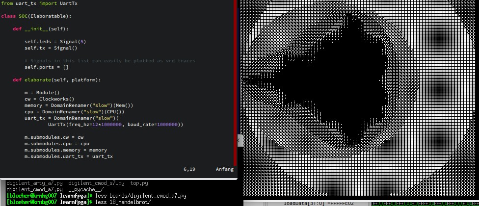
At that point, I had enough experience with Amaranth to tackle the tutorial as a practice exercise. Instead of using verilog, I followed Bruno’s tutorial in Amaranth HDL, using the open-source F4PGA (formerly Symbiflow) toolchain and an FPGA board that was not supported in the tutorial (Digilent CMOD A7 with Xilinx Artix 7). I wanted to see how far I could go and was unaware of the obstacles that lay ahead.
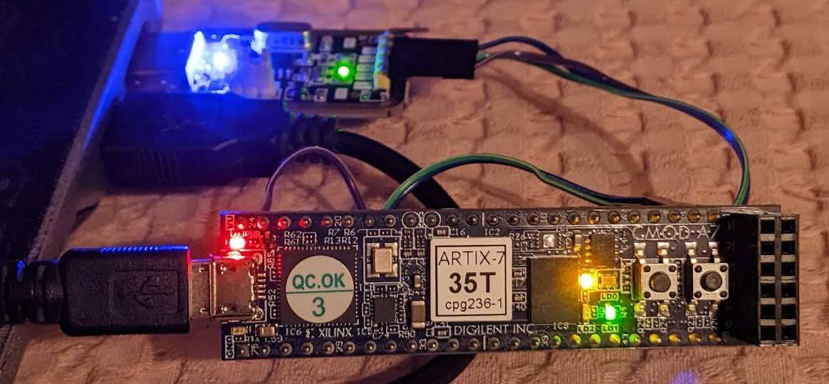
Digilent CMOD A7 FPGA board with Xilinx Artix7. USB-UART dongle in the back.
# And get going!
I started the course in December 2022 and published the first version, including step 18 (mandelbrot generator), by the end of February 2023. Here are some of the things I learned during these three months: even though I had used Amaranth HDL before, I needed to learn a few more tricks to translate the tutorial code. I learned how valuable instant feedback through test benches and simulations can be. Most of the time, if the simulated logic was working correctly, the hardware implementation was doing the right thing. I had long wondered what makes a CPU a CPU: what are the essential parts, and how do they all work together to execute a set of instructions and manipulate memory and/or pixels on the screen?
This is the question that the tutorial answered in great detail in the first 18 steps and unraveling the mystic black box that a CPU usually is, contributed to at least half the joy I experienced while putting together my own CPU. Bruno explains the RISC-V ISA and ABI, and together we build a more and more capable version of the processor step-by-step. At the same time, I learned the corresponding assembly language for RISC-V, which is essential for testing and programming the CPU at every step. The later steps focus on compiling third-party code with GCC and how to configure the linker so that code is executed from the correct piece of memory in the FPGA. I also learned a lot about compiled objects and ELF formats, which one usually doesn’t have to worry about when compiling for Linux-based systems.
# There’s more to it!
In addition to the obvious takeaways, there were also several unexpected events that occurred along the way. One significant obstacle was that Bruno’s tutorial came with a custom RISC-V assembler, written in Verilog, which assembled the instructions while compiling or simulating the logic. This meant that I had to figure out how to seamlessly integrate it with Amaranth. Moreover, I had to fill in jump offsets manually, which is not very convenient. To streamline the process, I went on a longer tangent to implement the assembler in Python. It was a challenging task, but I succeeded in achieving seamless integration with Amaranth, without the need for manual jump offsets. At a later step, Bruno incorporates the tiny UART sender by Olof Kindgren, I successfully ported it to Amaranth as well, which was a pleasant surprise since it almost worked on the first try.
However, when I attempted to compile for the FPGA boards I had on hand, I realized that they were not supported by the amaranth-boards repository. Fortunately, I was able to modify a similar board description with the help of the reference manual for my hardware (and even get the code merged in time for this post). Meanwhile, I also discovered and fixed a bug in Amaranth itself, as well as some typos in Bruno’s tutorial. On more than one occasion I found out that I can effectively discover my own bugs by actually executing code on the CPU. I also learned how to use many great tools, such as Yosys, openFPGAloader, GTKWave, Verilator, and Edalize.
I’m currently working through the last parts of Bruno’s tutorial, and while I still have a few steps to go, I’ve already learned a lot. Converting the examples to Amaranth HDL has been challenging, but not impossible. Personally, I enjoy working with Amaranth because its semantics are clear and it offers the full power of Python when needed. While some things are more verbose in Amaranth (such as Mux() and Repl()) than their Verilog counterparts, others can be written more concisely.
# I could not have done it alone
During the process, I’ve had many questions about Amaranth, the build system, the toolchain, and the hardware. Luckily, the helpful community on IRC (#amaranth-lang on libera.chat) and GitHub has always been quick to respond. Additionally, documentation for open toolchains and developing with these tools has greatly improved in the past year.
Still, some endurance is needed to pull through, when things don’t work as expected. For example, my board and one of my chips were not supported by Amaranth, and I encountered issues compiling on an older laptop with an unsupported 32-bit host architecture. I also found myself in python package hell on more than one occasion. And as they say, the devil is in the details, since some seemingly small steps have taken considerably more time than anticipated (“proceed after you have a working RISC-V assembler”, “we’ll use this existing UART module”, “now just convert the ELF to HEX format”).
# Final thoughts
Despite these challenges, my plan is to continue with the tutorial and get the SPI interface working. In the meantime, I’m also working on getting support for the free Gowin toolchain (project apicula) into Amaranth’s build system. Looking ahead, I’m excited to apply the things I’ve learned from (not strictly) following Bruno’s tutorial to other projects. I’d also encourage anyone interested in these concepts to take their favorite HDL and port the tutorial. For me, this has been a great experience, and I’m certain that with a growing user base, FPGA design will become even more accessible than it is today!
# About the author
Dr. Bastian Löher (Twitter: @y__, Mastodon: @bl0x@mastodon.social) ported Bruno Levy’s FPGA tutorial to Amaranth HDL. He is a physicist and control systems engineer for nuclear physics experiments with heavy ion beams. He designs efficient data acquisition software for large heterogeneous particle detection systems and builds mobile radiation sensors for fun.