This guest post is by Aki Van Ness.
# Sky130 SPICE, the KiCad way
Picture this, you’re working on a custom layout for Sky130, be it a PLL, or you’re just trying your hands at making some basic building blocks. You’ve got a plan, and and ready to start laying down some nets, and that’s when you must face it, the dreaded xschem!
All joking aside, xschem is an incredibly powerful schematic capture system, but that power comes at a cost. xschem is fairly arcane to most, it has some graphical problems, and is just in general really hard to use if you’re just starting out which makes rapid iteration difficult.
Enter KiCad, a robust and Open Source EDA software package, while it is mainly used for PCB layout, we can leverage the schematic capture and built-in SPICE simulation, right?
# Introducing kicad-pdk-libs
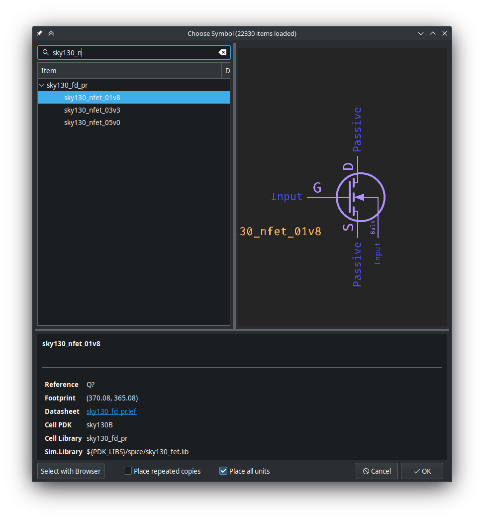
A little while ago I ran into that exact problem, and so I set out and made kicad-pdk-libs, a KiCad symbol library that adds schematic symbols for not only the basic building blocks of the Sky130 PDK, but also SPICE library linkage.
With this you can do things as simple as just stubbing out a SPICE simulation for some of the primitive gates, or go down to the transistor level and build gates from scratch and simulate their characteristics!

As it stands, kicad-pdk-libs has almost 100% complete symbols for both the Sky130A and Sky130B PDKs, all the cell libraries as well as the base sky130_fd_pr primitives library. This allows you to not just put transistor level schematics together, but much larger schematics using all of the pre-made gates and cells in the library, including some SRAM blocks.
# Quick n’ Dirty Inverter
The basic example that almost everyone uses as their first CMOS device is the trusty inverter. As such we will quickly go over it here, if you wish for a more step-by-step guide with additional details, see the kicad-pdk-libs intro in the docs.
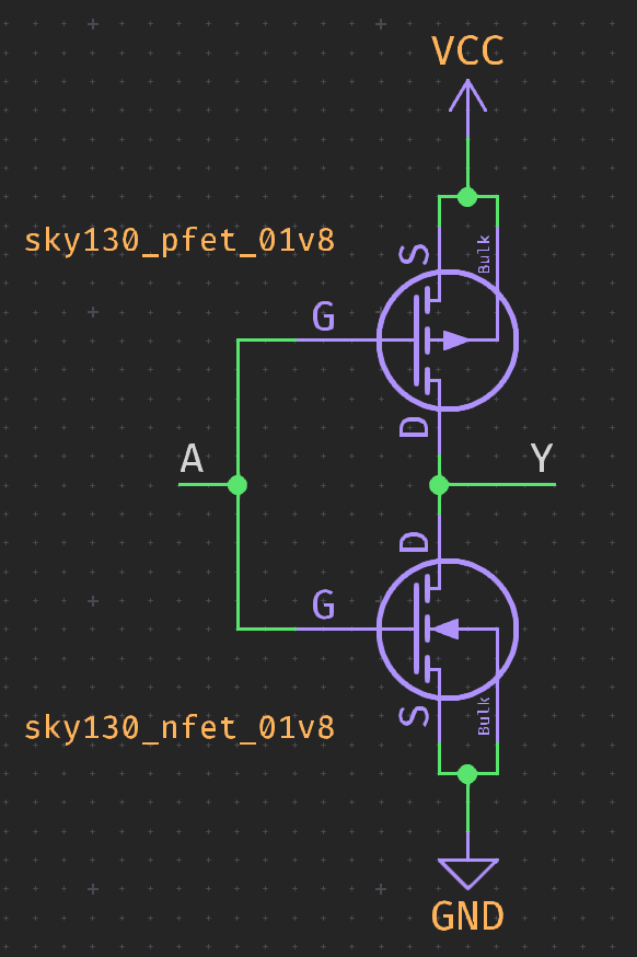
All you need to do is to throw a sky130_pfet_01v8 and a sky130_nfet_01v8 on top of each other with their drains facing each other, hook up VCC and GND and then join the gates and drains, and just like that, you have an inverter using the primitive Sky130 FET models.

Next set up some way to drive the sim, in my case I did a VDC source and then a VPULSE to drive the inverter, these are built-in to the standard KiCad SPICE library, it should look something like this when done:

After that, you can add the following SPICE directives as a text element on the schematic, and make sure to replace ${PDK_ROOT} with the path to your local PDK root:
.tran 100f 100n
.lib ${PDK_ROOT}/sky130A/libs.tech/ngspice/sky130.lib.spice tt
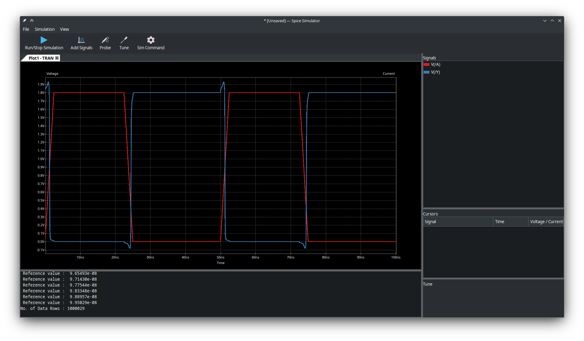
And finally, we’re ready to run the sim! Open up KiCad’s simulation utility and simply click the “Run/Stop Simulation” button, if all goes well, the simulation will run and then we can plot the A and Y signals.

Look at that! It’s a working inverter!
Something important to note, this simulation uses default parameters for the Sky130 transistors, you can get more accurate results by using magic to extract the transistor parameters from a layout and then attach them to the KiCad symbols by setting the Sim.Params property on the transistor.
# Conclusion
I hope this gives you a brief idea of what the kicad-pdk-libs is all about, and how you can use it to simulate your schematics for use in ASIC layout.
While it may not be as powerful and scriptable as something like xschem, especially right out of the box, I hope it is a useful tool for those just starting out, or for people who just need to throw things together quickly. Especially with the promising improvements coming to KiCad 8’s simulation workspace, which will allow much more comprehensive and complete analysis.
If you’re interested in kicad-pdk-libs and what you’ve read here, give it an install, and check out the intro and the examples for more detailed information.
Go have fun and make something cool!
