This guest post is by Gabriel Gouvine.
Applying logic locking to a TinyTapeout design with Moosic
When creating a design, most of us are not in possession of the lithography and manufacturing tools necessary to actually create the chip: we send our design to a foundry and they make the chip for us.
This requires a great deal of trust in the toolchain and the foundry: a malicious actor could introduce backdoors, or just steal the design to reuse it themselves. For security-conscious designers, countermeasures are necessary.
One such countermeasure is logic locking: we are going to lock our design, so that it does not work without a secret key. We do it by adding or changing some gates in the design to use the key: if the key is incorrect, the design behaviour will be completely modified. This is going to make it harder to reuse the design without authorization (you have to find the key) or to introduce backdoors (you have to understand what it does).

We built a Yosys plugin to do just that.
The plugin provides a logic_locking command that will mangle the design as much as it can.
To illustrate, let’s make a design on TinyTapeout, lock it and synthesize it all the way to silicon.
What is logic locking
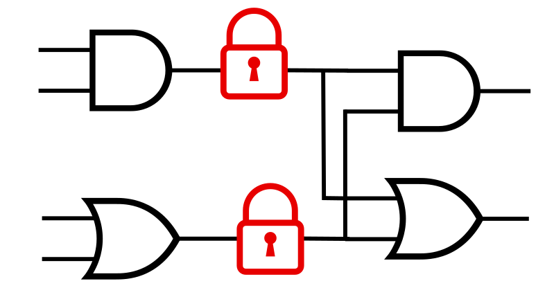
The goal of logic locking is to make the design unusable without the right key. Usually, we apply it after synthesis, when the design is already mapped to logic gates. Logic locking adds new gates that will change the behaviour of the design unless the right key is provided. Our tool does it by adding Xor and Xnor gates, as shown below, but you can imagine a lot of ways to insert or replace gates. If a 0 is set for a Xor gate, or a 1 for a Xnor gate, the design works as before. It acts as a countermeasure rather than a cryptographic security. Much like software countermeasures it will not stop a determined attacker with unlimited resources, but it’s one more thing that an attacker will have to break.

The logic locking tool needs to decide where to insert the gates. Its goal is to disrupt the design as much as possible, and ideally make the key hard to guess by running and analyzing the design. The tool will analyze the impact of inserting a locking gate, and pick the places that maximize its estimated security, typically signals that have a large impact on the design’s behaviour. Ultimately, it’s a tradeoff between security and performance: for security, the more gates you insert the better, but this makes the circuit bigger and slower.
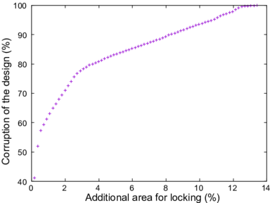
Just a few percents of the gates locked is almost always enough to completely corrupt the design. We can explore the tradeoff with the plugin. For example, on this benchmark, locking just 13% of the signals breaks all outputs and all testcases:
Locking a design
We are going to make a toy design to experiment with logic locking. I wrote a counter, that is incremented at each clock cycle where do_incr is set:
module counter (
    input wire do_incr,
    output wire [7:0] data_out,
    input wire clk,
    input wire rst_n
);

reg [7:0] counter;
assign data_out = counter;

always @(posedge clk) begin
    if (!rst_n) begin
        counter <= 0;
    end else if (do_incr) begin
        counter <= counter + 1;
    end
end
endmodule
We run Yosys with the Moosic plugin. Since logic locking works on a netlist, we first synthesize our counter with the default library:
read_verilog src/counter.v
synth
Now we apply locking and save our netlist. To fit in our 8-bit input port, I picked a small 6-bit key. With only 64 possible values, it is easy to brute-force, so make it a lot bigger if you use it in the wild! And don’t lose the key.
logic_locking -key-bits 6 -key 39
write_verilog src/locked_counter.v
Looking at the file, our module is now a netlist with an additional port moosic_key. Following TinyTapeout’s philosophy, it all runs as a Github action.
module counter(do_incr, data_out, clk, rst_n, moosic_key);
  input do_incr;
  output [7:0] data_out;
  input clk;
  input rst_n;
  input [5:0] moosic_key;
TinyTapeout
With TinyTapeout, we can synthesize this design to silicon. We will have to make a wrapper in order to load the key on our design… and test that our design works as expected when the key is provided. The main project file will be responsible for loading the key. We are going to keep it simple and read the key directly from the primary inputs. On a production design, getting the key in would be part of the boot sequence.
To make sure it all works, we wrote a testbench that checks that our counter behaves as expected… and is indeed broken with the wrong key.
And finally we have the full masks for the design! The code for the TinyTapeout project is available here, and our locked counter will be on the TT06 chip when it tapes out. If you want to go further, have a look at the project page or our Free Silicon Conference presentation.
For power users, the plugin provides a lot of additional options to pick your security metrics, or to balance security and performance. Logic locking is an active area of research, and we are happy to provide an open-source tool to apply it to your designs.